
Lathe machines are machine tools that rotate a workpiece about its axis while a cutting tool removes material to produce cylindrical or conical shapes. Operators set up a blank between a headstock and tailstock or secure it in a chuck, then control relative motion between tool and workpiece to perform turning, facing, boring, and grooving. The process relies on predictable material removal, where geometry of the cutting tool, the rigidity of the setup, and the selected cutting parameters together determine surface finish, dimensional accuracy, and cycle time.
The mechanical and operational principles include spindle speed, feed rate, and depth of cut as primary variables that influence metal removal rate and tool wear. Cutting tool materials and angles may be chosen to suit the workpiece material and intended operation. Workholding method and machine rigidity can affect vibration and concentricity. Heat generation and chip evacuation are managed by coolant, cutting speed adjustments, and tool geometry considerations to maintain consistent machining conditions and part tolerance.
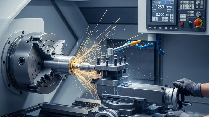
Conventional engine lathes may offer a wide range of manual control and fixturing flexibility, which can be advantageous for one-off parts and learning turning fundamentals. They can require skilled setup to achieve repeatable results and may rely more on operator judgement for feeds and speeds. For certain materials, operators may often select conservative cutting parameters to reduce chatter and extend tool life. Typical workshop practice includes verifying spindle runout and ensuring secure clamping before machining to reduce dimensional error.
CNC lathes can typically maintain tighter tolerances through programmed compensation and automated tool changes, which may reduce cycle variation across batches. They often support multiple cutting tools and live tooling for milling features on turned parts. Programming may consider tool life cycles and tool offsets; monitoring parameters such as cutting temperature and tool wear can inform adaptive adjustments. CNC setups commonly use preset tooling and probe cycles to improve first-piece inspection and reduce setup time compared with purely manual methods.
Turret lathes may reduce non-cutting time by keeping several tools mounted and indexed rapidly, which can be useful in workflows that repeat a sequence of turning, facing, and parting operations. Tool turret indexing speed and turret capacity typically influence throughput. Tool geometry selection for turret operations often favors robustness to handle interrupted cuts and maintain tool life across repeated cycles. Operators may plan turret layouts to sequence tools in a way that minimizes retraction and travel between operations.
Cutting parameters—spindle speed, feed, and depth of cut—interact nonlinearly and typically require balancing for desired surface finish and tool life. Higher cutting speeds may increase productivity but can accelerate wear depending on material and tool grade. Feed affects surface roughness and chip load per tooth on multi-point tools, while depth of cut determines material removal per pass. Machining plans often document parameter ranges that may be empirically adjusted during initial trials to account for specific material batches, tool condition, and machine rigidity.
Control of tool geometry and material choices can influence chip formation and heat distribution during turning. Positive rake angles may reduce cutting forces for ductile materials, while negative rake may be chosen for interrupted cuts or hard materials to strengthen the cutting edge. Coated carbide grades often extend tool life in higher-speed applications, whereas high-speed steel tools may be preferred for low-volume or manual work where toughness and ease of grinding are useful. Tool holding stiffness and proper insert clamping can also reduce vibration and improve surface integrity.
In summary, understanding machine type, typical turning operations, cutting parameters, tool geometry, and workholding methods forms the foundation for consistent lathe machining. Each element may influence the others: machine rigidity can affect achievable cutting speeds, and tool choice can dictate feed rates that maintain acceptable surface finish. The next sections examine practical components and considerations in more detail.

Each machine type introduced on the first page supports a set of common applications that may align with workshop scale and part complexity. The conventional engine lathe often serves repair, prototyping, and education contexts where one-off parts or low-volume runs are common. CNC lathes may be used for production runs with complex contours, where repeatable tool paths and automatic indexing reduce per-part variation. Turret lathes can be effective for sequential operations in medium-volume production, where rapid tool changes via the turret reduce cycle time without full CNC control.
Selection between these types often involves trade-offs in flexibility, setup time, and throughput. Conventional lathes typically require more manual intervention and skilled operators but may be cost-effective for variable work. CNC lathes may require upfront programming and fixture development that can be justified when repeatability and per-part consistency are priorities. Turret lathes can offer a middle ground by enabling quick multi-tool sequences with less programming than full CNC systems, though turret indexing and tool life must be managed carefully.
Material considerations influence how each lathe type is used. Ductile steels and aluminum commonly machine well on engine lathes with standard carbide or HSS tooling, while high-precision components from stainless steel or hardened alloys may typically be processed on CNC turning centers with specialized inserts and coolant control. Turret lathes may handle softer steels and brasses in repetitive operations where interrupted cuts or profiling are planned. Operators usually document material-specific parameter ranges to guide initial setups across machine types.
Practical considerations for workshop planning include availability of tooling, fixturing, and trained personnel. Conventional lathes may require more in-process adjustment and manual inspection, while CNC systems can integrate probes and tool setters to standardize setups. Turret setups may emphasize rapid turret layout and spare tooling to minimize downtime. These operational factors often guide whether a facility uses multiple lathe types in combination to balance flexibility and productivity.
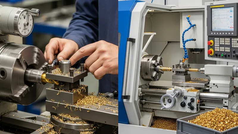
Turning operations such as straight turning, facing, boring, grooving, and parting rely on selecting appropriate cutting parameters that interact with material properties and machine capability. Spindle speed typically relates to cutting speed (surface feet or meters per minute) and may be constrained by tool material limits and heat generation. Feed rate influences surface finish and chip thickness; higher feeds generally increase roughness but can improve material removal rate. Depth of cut controls the volume removed per pass and directly impacts cutting forces and required spindle torque.
On conventional engine lathes, operators may start with conservative feeds and speeds and adjust based on tool wear and surface condition. CNC lathes often allow parameter tables in the control to vary feed and speed automatically for different tool paths; adaptive controls may modulate parameters in response to sensed loads. Turret lathes, used in repeated sequences, may keep parameters constant across cycles to maintain rhythm, but operators typically monitor for signs of tool fatigue or thermal drift that can indicate the need for parameter adjustment.
Cutting fluids and chip control methods interact with parameters and tool geometry. Effective coolant application can reduce cutting temperature and extend insert life in higher-speed operations, and chip breakers on inserts can improve evacuation in long-chipping materials. For each lathe type, planning for chip management—tray design, coolant flow, and guard placement—may reduce downtime and improve operator safety. These considerations often form part of initial process documentation and ongoing monitoring.
Monitoring and measurement provide feedback to refine parameter selection. Surface finish measurements, dimensional checks, and tool wear assessments may inform incremental adjustments. In production runs on CNC and turret lathes, statistical process control charts and tool life logs may typically be used to schedule insert changes before dimensional drift occurs. Such practices help stabilize process outputs across batches without relying solely on operator judgement.
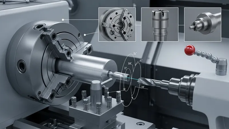
Workholding choices introduced on the first page—chucks, centers, and turret-mounted fixtures—affect runout, concentricity, and vibration. Three-jaw chucks are common for cylindrical parts with reasonable concentricity, while four-jaw independent chucks allow off-center and irregular shapes. Collets offer high repeatability for short, consistent-diameter parts. Tailstock support with centers or live centers typically reduces deflection on long slender workpieces. Each method may require attention to clamping torque and seating to avoid distortion or slippage during cutting.
Tool geometry must match both the operation and the workholding arrangement. Rake and clearance angles influence cutting forces and surface integrity; a neutral or slightly positive rake may reduce forces on flexible setups, while tougher negative-rake geometries may be preferred for interrupted cuts. Insert nose radius affects surface finish and form accuracy; larger radii can improve surface finish but may increase cutting forces. Proper tool overhang and holder rigidity are considerations to minimize chatter, particularly on long-reach setups.
Setup procedures often begin with ensuring spindle and tailstock runout are within acceptable tolerances and that clamping devices are clean and functioning. Tool offsets and zero references are established using indicators or probe systems, especially on CNC lathes. For turret lathes, indexing repeatability and turret backlash are monitored because small errors can accumulate across sequential operations. Documenting setup steps and verifying critical dimensions before full production runs is a common practice to reduce scrap and rework.
Secondary considerations include balancing of long parts, guarding against chip entanglement, and verifying coolant paths to avoid thermal gradients that might shift part dimensions. Fixturing that distributes clamping forces evenly may reduce surface marring and distortion. These setup-focused practices are often recorded in process sheets to help operators reproduce consistent conditions across shifts or when moving work between machines.
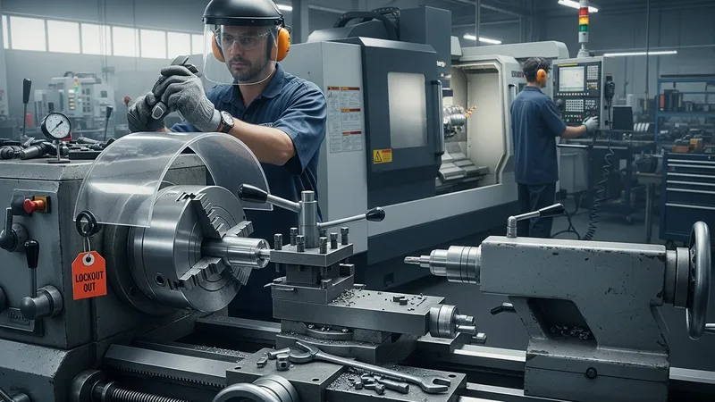
Safety practices align closely with machine type and operation. Basic safeguards include ensuring guards are in place, selecting appropriate personal protective equipment, and avoiding contact with rotating parts. On conventional lathes, operators may be more exposed to manual tool changes and must follow lockout procedures during setup. CNC machines typically incorporate interlocks and enclosures that reduce direct exposure, but programmers and operators remain responsible for safe program verification and proper fixturing to prevent thrown workpieces.
Routine maintenance supports predictable performance across the machine types introduced earlier. Maintenance tasks typically include lubrication of ways and headstock bearings, inspection of spindle runout, checking tightness of chuck jaws and turret mechanisms, and cleaning coolant systems to prevent pump or nozzle blockages. Scheduled inspections and record-keeping for tool holders and spindle condition can help identify wear trends before they affect part quality. Such practices often reduce unplanned downtime and contribute to stable machining conditions.
Common applications across these lathes include shafts, bushings, threaded components, and stepped geometries that require concentricity and controlled surface finish. CNC lathes may produce complex profiles and integrated features where tolerances are critical, while turret lathes may be selected for repetitive operations on simpler turned parts. Conventional engine lathes remain valuable for maintenance work, custom one-off parts, and situations where fixturing or part access is more readily managed by an operator than by automated tooling.
Overall, combining attention to safe operation, consistent maintenance, and process documentation helps maintain part quality and machine availability. Practitioners often use a mix of these lathe types within a facility to match process needs with machine capabilities, and iterative measurement and adjustment are typical to refine cutting parameters and tooling choices over time. The article has focused on descriptive, operational considerations to help readers understand how machine type, tooling, and setup interact in turning processes.